
Recommissioning of a Telefunken M15 studio tape recorder
Part 1: A 50th birthday tribute
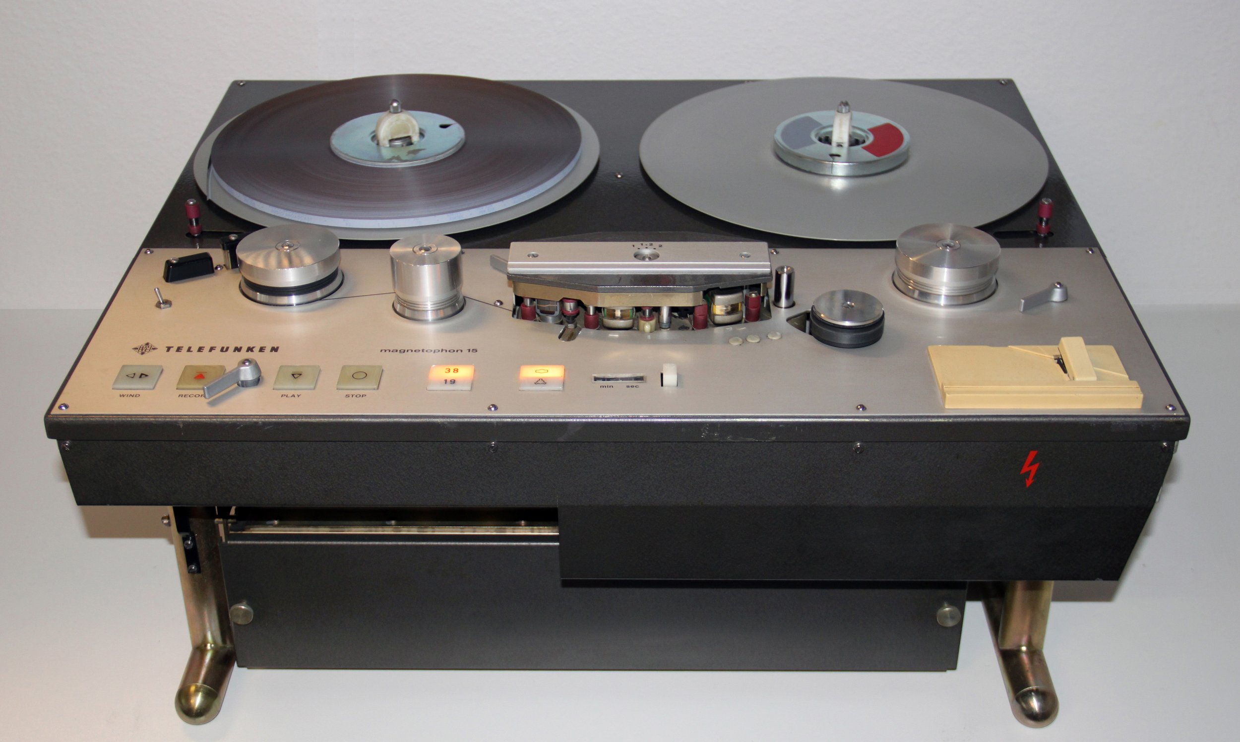
Figure 1: General view of the Telefunken M15
The Telefunken M15 studio tape recorder was first introduced at the Hanover Fair in April 1971. It incorporated the discrete transistorized circuit boards "V 396" and "V 397" from the predecessor series M10A, but was equipped with a new mechanical control system, which was also largely retained in the subsequent series, the M15A. The M15 was replaced by the M15A in 1976 after a construction period of five years. For me, the M15 is the perfect mixture of the two worlds of the M10A and the M15A: Mechanically on the then state of the art, which could hardly be improved even years later, and electronically in the best transistor circuit design, before this was replaced in the M15A by integrated circuits (ICs), which are said to have a cooler sound characteristic.
If you can get hold of a Telefunken M15 in a good condition on the market, you can consider yourself lucky. These devices follow an extremely robust development concept. Most components are oversized several times and thus very durable. Almost all mechanical and electronic components are easily accessible. This development is a reference class of serviceability.
The unit presented here was acquired by the Deutsche Oper Berlin in the early 1970s. In 1992, Radio NRW bought it. In the same year, it was used at the Summer Olympics in Barcelona, together with a second M15 for editing the radio reports. In 1995, it was used by Hellweg Radio, a local station for the district of Soest, Germany, to listen to the last tapes still in circulation. A few years later, a friend of mine bought it. In 2018, I purchased the unit and so it's back in Berlin, just four kilometers from the Deutsche Oper as the crow flies. In a first functional test, the device played but showed a few flaws.
The mechanical and electrical characteristics (housing, motors, control system, etc.) of the M15 are very similar or identical to the successor model M15A. Many explanations in this article thus apply to both models. The biggest difference of the M15 are eleven discrete circuit boards for the audio electronics. The M15A, on the other hand, gets by with five plug-in boards. The adjustment possibilities are the same, only the potentiometers are distributed in a different arrangement on the boards. The boards in the drive magazine (back) are also different. The user manual for the M15 is concise, which assumes knowledge for maintenance. A technical education would be an advantage for the user. Nevertheless, this article can also serve for functional testing by the layman who acquires the knowledge e.g. autodidactically. The warning against the life-threatening mains voltage of 230 volts must not be omitted here: Please observe the rules for such an application and, in case of doubt, have the work carried out by qualified personnel. This also applies to all moving and rotating parts: Body parts getting caught or hair getting wound up, loose pieces of clothing or similar pose a high risk of injury. All the information contained in this article are practical tips, primarily for understanding the function of this tape recorder. This article is about the author's analysis and experience. It may contain errors. Also for this reason, I ask that if you try to copy it, you do so at your own risk and responsibility. The author is not liable for any damage to the equipment or personal injuries or accidents.
Of course, the joy is great when the almost 50-year-old device with a weight of 53 kg stands in front of you. Connecting the power cord and pressing the power switch would satisfy the first curiosity, however, I would like to recommend checking a few things before this action. If you have an adjustable mains isolation transformer, you can slowly increase the mains voltage from zero volts when the machine is switched on and see if the machine draws an excessively high current even at low voltages, which would certainly cause a fuse to blow or the electronics to malfunction at full mains voltage. If there is no isolating transformer, the only option is to press the power switch. The unit has eight fuses on the rear panel, which normally blow in the event of a fault.
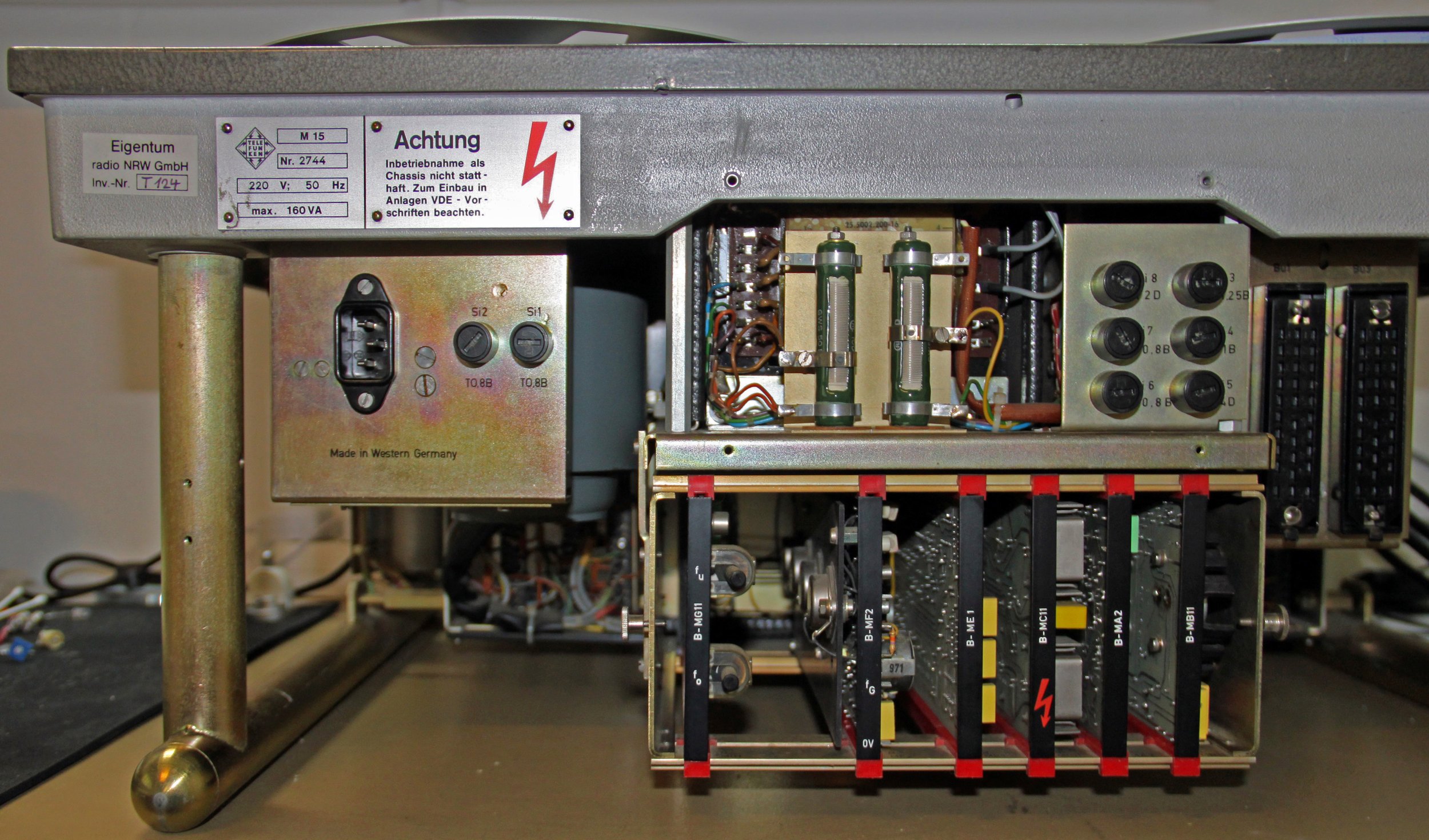
Figure 2: Rear view with covers removed
Before switching on the tape machine (power cord not plugged in)
Before turning on or purchasing a machine, a visual inspection should be performed. This can reveal defects that indicate damage.
Stand damage
These are primarily traces of water, mold, dust and dirt. Caution is advisable, especially in the case of basement or attic finds. Moisture and temperature differences leave marks on all parts of the equipment, but especially on moving parts and connectors. Loose dust can be removed with a vacuum cleaner. If it sticks strongly, it can be loosened with a soft brush and vacuumed off. For stubborn dirt, there are various cleaning agents. I recommend always starting with a mild agent first and only gradually proceeding with stronger chemical "weapons". Industrial dust that smears when wiped off can be tackled with cleaning gasoline. A white rag will show the removal of dirt. Care should be taken with painted and lettered surfaces.
Surfaces, sockets and plug connectors
It often happens that the hammered lacquer on the surface of the chassis has been damaged by ground-in "coil rings". This happened due to bent winding plates or due to manual braking in the cutting studio, when stopping the plates was not fast enough for the personnel. Although the paint is very robust, it rubs off when, for example, a machine standing on its side slips on a hard and irregular surface. With a weight of about 53 kg, this is logical. The only thing that helps here is to have the cover repainted.
Bent parts are practically never found on the chassis or the stand legs. However, the covers are often bent or compressed. Usually it does little good to bend them into position because they are basically deformed and the metal or folded edges are warped. Some dealers disassemble the machines, which is why you can find replacement parts on the Internet, often even affordable, because the metal parts are not part of the first line of parts for sale.
On some machines, the Tuchel plugs and jacks were removed and replaced with an XLR variety. These were often installed at an angle and fastened with only one screw or glued to the frame. This was also the case with the unit shown here. I got an original and very well preserved Tuchel set at an online auction house for an amazingly low price. For soldering the balanced cables, it is important to have a reference unit or to study the schematics carefully, so as not to mix up the "hot" and the "cold" conductor.
Circuit boards
Before pulling out the audio boards, I consider it extremely useful to mark them so that they can be put back in the same position. Then the channel assignment is also preserved. The connectors are not coded, so they would fit into any slot inside the magazine. If the contacts are tarnished black, it is usually sufficient to clean them with cleaning gasoline and a soft cloth or brush and carefully plug and unplug the boards several times. The contact strips used by Telefunken are of very high quality and will last forever if handled properly (see also Figure 5 and Figure 6 of the V 397 a boards).
After unplugging the boards, they can be cleaned carefully. Dust can be loosened with a soft brush and vacuumed off. I would refrain from using compressed air, because it can damage the fine wires of transformers or compress dust in coils.
Potentiometer
Usually even the approx. 50 years old potentiometers on the boards still work. Contact spray should be the last choice to make them common. It makes much more sense to leave everything as it is and first see if the calibration values are still correct. An M15 is of such high quality that this is often still true with decades old settings. If the potentiometers have to be turned, I suggest not to turn them jerkily or with high force from one side to the other, but to loosen them with feeling. Sometimes a soft click can be heard when doing this. Then the slider can be carefully moved over its path several times. Once you have remembered what the setting was before, it is helpful in terms of faster calibration to move the slider back to the previous position.
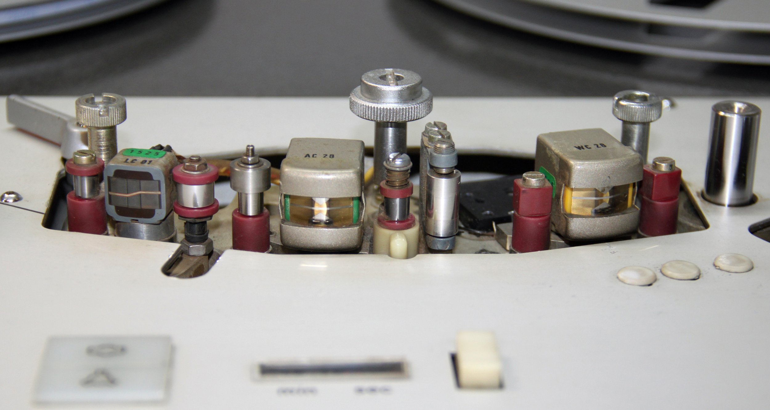
Figure 3: Tone head bridge Telefunken M15 with international layering
Tone head bridge
The sound heads are the central components for playing and recording music. If they are heavily worn, I can only advise against buying a machine. Equipped tone head bridges are usually overpriced on the market. This is also true for single tone heads with a good state of preservation. Telefunken's idea to make the tone head bridge exchangeable via two central screw connections is ingenious. After unscrewing the cover, two large knurled screws are found, which can be loosened or locked with a coin. Thus, the bridge can be removed, cleaned, demagnetized and then reinstalled 100% the same. Please do not turn the screws too tight, this would not put the bridge in a better position.
Used machines often have clay heads and tape guides that are heavily soiled or stuck together with tape abrasion. It is essential to keep metallic objects away from all parts around the head bridge when cleaning. Cotton swabs, a soft cloth, and mineral spirits or rubbing alcohol should be the tools of choice. Stubborn residues can be carefully tried to loosen with a toothpick or a chip card. Once adhesive residues and other dirt have been removed, the condition of the heads can be checked. If the surfaces have been symmetrically ground in by the passing tapes, this is usually less of a problem. If they look worn on one side, this is not a good sign. In case of doubt, the only thing that helps is to try them out. Above all, more accurate results will show up when the device is calibrated.

Figure 4: Drag switch and brake on the left, driving plate disassembled.
Drag switch
The function of the drag switches is essential for operation. If it is not, the control system of the machine will "go haywire". Absolute caution is required here, since the tapes can be wound up quite nastily or also stretched or torn off (tape tangle!). A lever mechanism (red marking, Fig. 4), triggered by a felt pad under the carrier plate, moves a magnet which switches the reed relay contact located in a vacuum glass bulb. This allows the control electronics to know in which direction the coils are moving at the moment of operation. You can test these switches by releasing the brake via the red lever mechanism and moving the black driver plate back and forth. You should then hear a soft click-click sound.
Rubber pinch roller
The belt is moved by being pressed onto the rotating capstan shaft by a rubber pinch roller. If the roller shows cracks or damage, it should be replaced.
Drive belt
The drive belt can be removed without having to disassemble the machine. Please be sure to disconnect the power cord first. On the M15, the front metal cover must be removed and the spring-loaded roller pressed to release the belt and free it for unthreading. Now clean the belt with spirit and a soft cloth. If the rubber shows severe cracks, the belt should be replaced. Check the capstan drive, the pressure roller and the motor for smooth running. If necessary, maintenance must be carried out according to the manual. Before reinstalling the drive belt, it should be rubbed with talcum powder. This increases the service life and reduces running noise.

Figure 5: Card V 397 a track 1 (before modification)
Figure 6: Card V 397 a track 2 (after modification)

Figure 7: Recording frequency response at 38 cm/s, red line with C21, yellow line without C21

Figure 8: Playback frequency response M15 with built-in capacitor C21 (8.2 nF)

Figure 9: Recording frequency response M15 with built-in capacitor C21 (8.2 nF)
Adapter board: Indispensable helper
For the repair of a circuit board, for the adjustment of the capacitor described above or for the measurement of values which can only be recorded via the measuring points on the circuit boards, the adapter board is very helpful. It fits the boards from both magazines.
After switching on the tape machine
Differences of the cards V 397 a, playback and recording frequency response
When comparing the playback cards V 397 a for track 1 and track 2 of the front card magazine, it was noticeable that some components were equipped differently.
On the card for track 1 the resistor R34 (100 kΩ) was assembled at a different place. Correction: The resistor R34 could be soldered to its new position on the board for track 1 by desoldering and realigning the legs.
Capacitor C21 (8.2 nF, tolerance 2%) was missing on the board for track 1. Correction: The capacitor C21 was retrofitted on the board for track 1.
The circuit diagram of the board V 397 a does not describe the function of capacitor C21. There is only the note "1) --- is used by the test field if necessary". It affects the bass range at the speed of 38 cm/s. With the WC 28 playback head used here, the level would drop rapidly below 80 Hz without compensation (see Fig. 7, yellow line). The equalization takes place in the playback equalizer. Since the playback frequency response overlaps the recording frequency response, the deviation is transferred accordingly. Reducing or increasing the capacitance did not improve the frequency response further in my case. C21 raises the low frequency range to such an extent that the playback frequency response could be aligned with a reference band to the values shown in Fig. 8. This results in the recording frequency response as shown in Fig. 9.
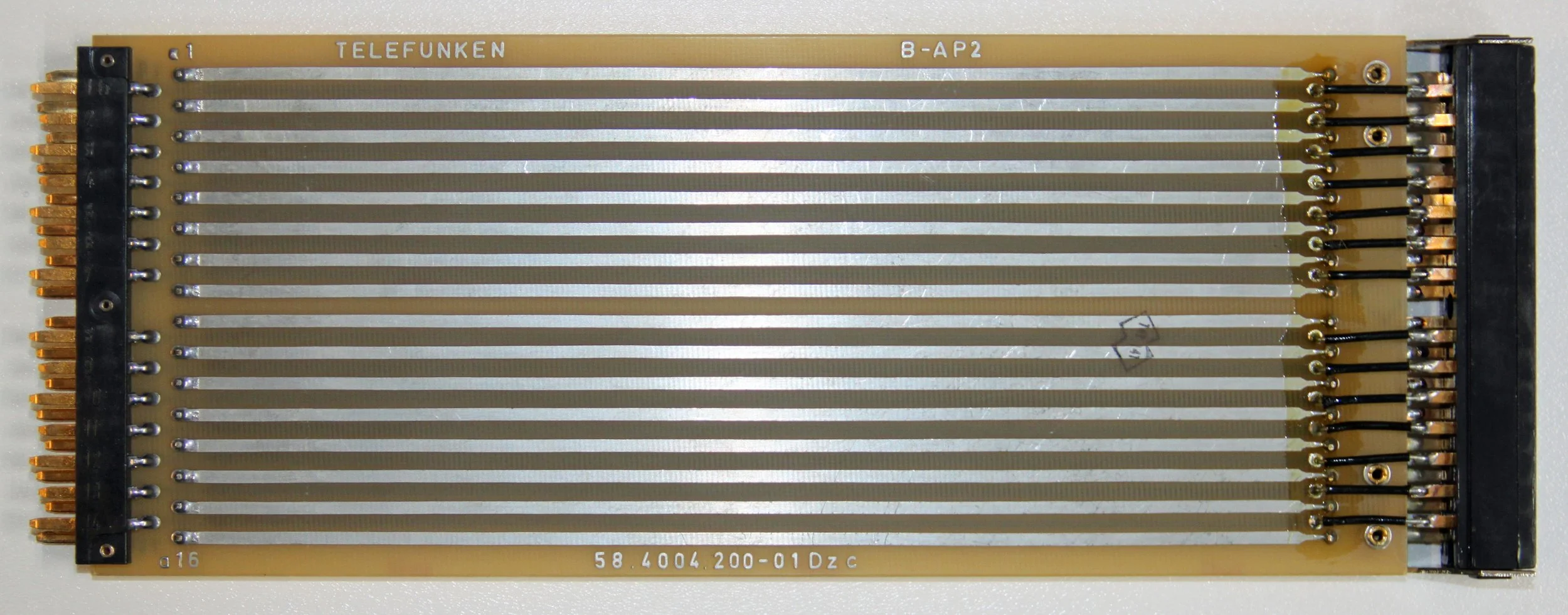
Figure 10: Original M15 adapter board

Figure 11: Front view M15 with disassembled apertures and installed adapter board
Reference or adjustment tapes
If you want to bring a Telefunken M15 into reference status with respect to playback and recording frequency response, you need appropriate reference tapes for 19 cm/s and 38 cm/s. On the market you can still find many tapes from the old stocks of the former manufacturers, but these, mostly 40 or more years old, are left to decay. In my search, I conducted an extensive test of supposedly well-preserved reference tapes. In addition, there were tapes from current production. Between all tapes I found deviating frequency responses with differences up to 6 dB. So what to do?
The tape specialist Uli Apel put me in contact with the tape expert Peter Ruhrberg. A very extensive conversation followed. Peter Ruhrberg, a sound engineer in his main profession, manufactures reference and adjustment tapes using very profound and far-reaching expertise. I purchased tapes made by him and am now very pleased that I was able to bring my M15 to reference status. If you are interested, please email Peter Ruhrberg. You will find his contact information at the end of this article.

Figure 12: Turntable for counter with LED

Figure 13: Counter LED with series resistor
Mechanical counter
The mechanical counter is usually defective on used machines. Either it does not run at all, does not count cleanly or can no longer be reset to "zero". This was probably the reason why many M15s were converted to electronic counters specially developed by studios. There was no conversion kit from Telefunken. If the mechanical counter still causes problems after removal and a thorough cleaning, it has to be replaced.
It is controlled by a stepper motor. This gets its signals from a rotating disk, which is operated by means of the left pulley. This pulley is located at the bottom of the chassis (Fig. 12). A light barrier is controlled by means of light/dark coding. If the bulb is defective, it can be pulled out of the socket. The bulb can be carefully unsoldered on the left and right and replaced by a clear LED with a series resistor of 4.7 kΩ. With the short leads to the components, care must be taken to ensure very short soldering times so as not to damage them or the plastic base (Fig. 13).

Figure 14: Light barrier in active mode

Figure 15: LED and replaced lamp
Light barrier (if present)
If a light barrier is present, it can be switched on and off with the adjacent toggle switch (toggle switch is optional). If the bulb is defective, a white clear LED with a diameter of 5 mm and a series resistor of 2.7 kΩ can be used. The voltage at the two pins for the bulb is approx. 14 volts. When the light barrier is activated, the tape stops after a glued-in clear tape strip passes by in playback and recording mode. The original function, that the light barrier could distinguish the colors of different leader tapes, is no longer given by the replacement with a LED.

Figure 16: Original winding plate
Figure 17: Trident adapter
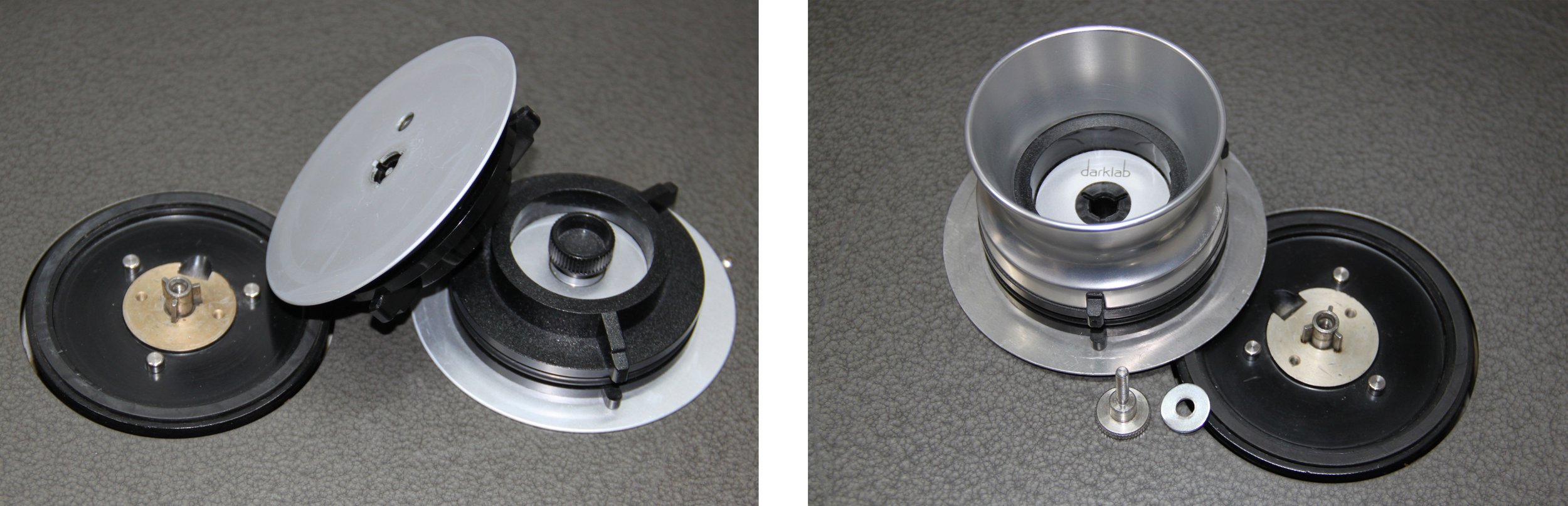
Figure 18: NAB adapter, simple version
Figure 19: NAB adapter, luxury version
Accessories for playing the different tape versions
Since my M15 has the international layer, it is predestined for playing reel-to-reel tapes. For NAB cores, the market offers different versions: If you like it simple, buy two inconspicuous adapters, which can be locked by the captive center screw (Fig. 18). Those who want to buy luxury adapters with anodized cups have it a bit more difficult: You need two additional knurled screws (thread M 4) with matching washers and two round aluminum plates (thickness: 1.2 mm; if necessary also 1.5 mm) to place the adapter and the coil a bit higher, otherwise the tapes will not be wound centrally between the boundaries of the coils (picture 19). Telefunken has thought along perfectly: The tape drives have the obligatory trident, although it is very short. A trident adapter can be screwed on via the internal thread (Fig. 17). The standard equipment includes the belt plate, plus the adapter for locking (Fig. 16).
Source information: Original Telefunken manual "magnetophon 15, ¼'' devices."
Measurements: Audio Precision ATS-2
Recommissioning of a Telefunken M15 studio tape recorder
Part 2: Operation in the living room

Figure 1: Telefunken M15 with trolley and hood
The Telefunken M15 tape recorder is not only big. Above all, the capstan drive unit makes a lot of noise at the speed of 38 cm/s. In addition, there are mechanical running noises as soon as a tape is running. These machines were not built to stand in the radio station's studio, but in an adjacent room where the broadcasts were prepared by the staff. There, several machines stood next to each other, which were started by remote control from the studio. With the measures described here, "the monster" is tamed visually and mechanically, so that listening is as much fun as possible without background noise, and the rotating reels can be watched, the salt in the soup of tape lovers!

Figure 2: Side view of the electrical and electronic connections
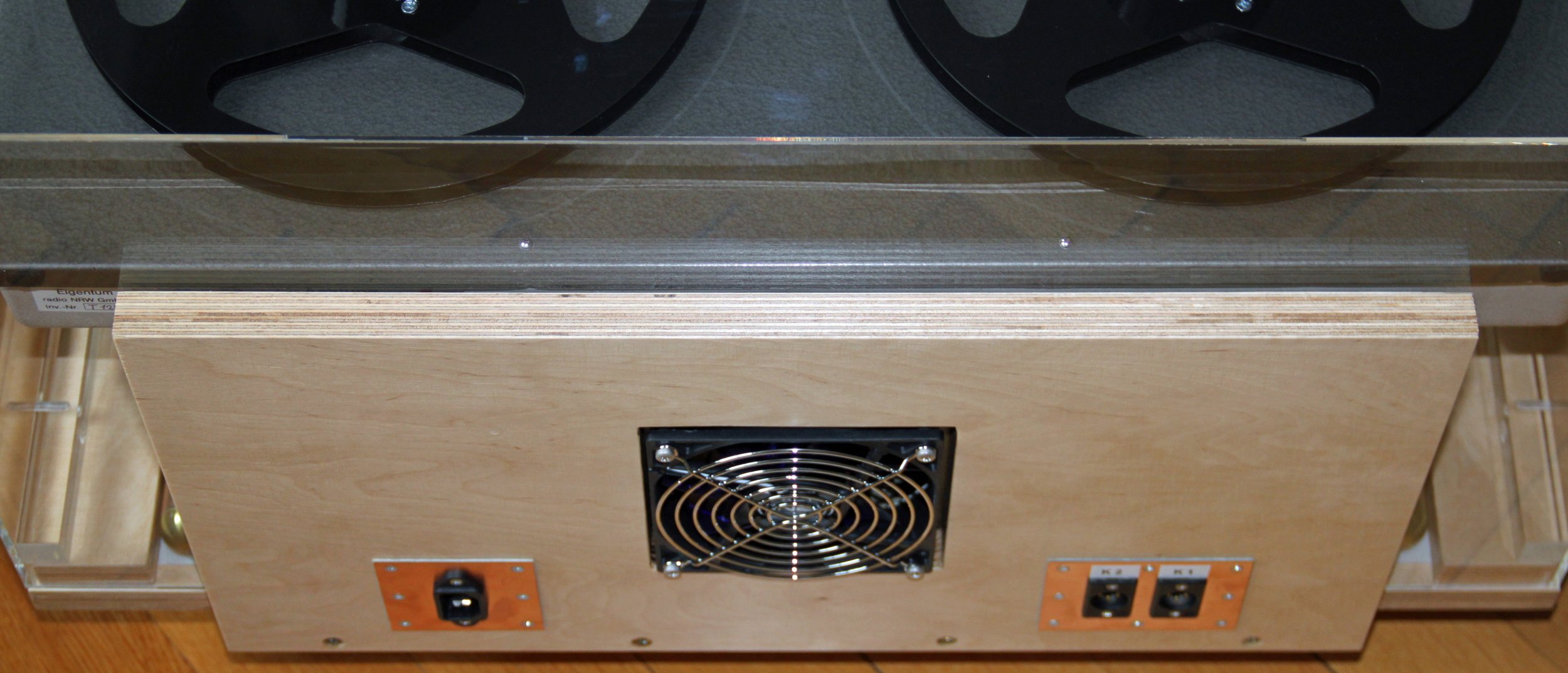
Figure 3: Sandwich construction of the rear side
Trolley with transparent cover
At first my thoughts went in the direction of building a cabinet for the M15. Then, however, the idea of visibility of the technology became established. In addition, there were practical considerations regarding access to the connections and the mobility of the unit. So it had to be a cart that carried the unit along with a clear hood. For ease of use, the hood had to be quick and easy to remove. After it was put on, it had to be as soundproof as possible. For this reason, I mounted lateral guides. To prevent mechanical vibrations on the wooden board, I placed the machine on felt mats. For the rear side, I devised a sandwich construction that allows a fan to protrude through a vertically mounted wooden panel and terminate with the wood on the inside with a self-designed housing for the fan unit. The hood was provided with a cutout. It is pushed between the wooden plate and the back of the M15 and closes with the wooden plate from the inside (Fig. 3).
If necessary, all supply lines can be removed. The trolley is then self-sufficient and can be moved to another location without the need for cumbersome cables in tow. To prevent the rollers from standing flat with a weight of approx. 60 kg, I spent a few euros more for quality goods.
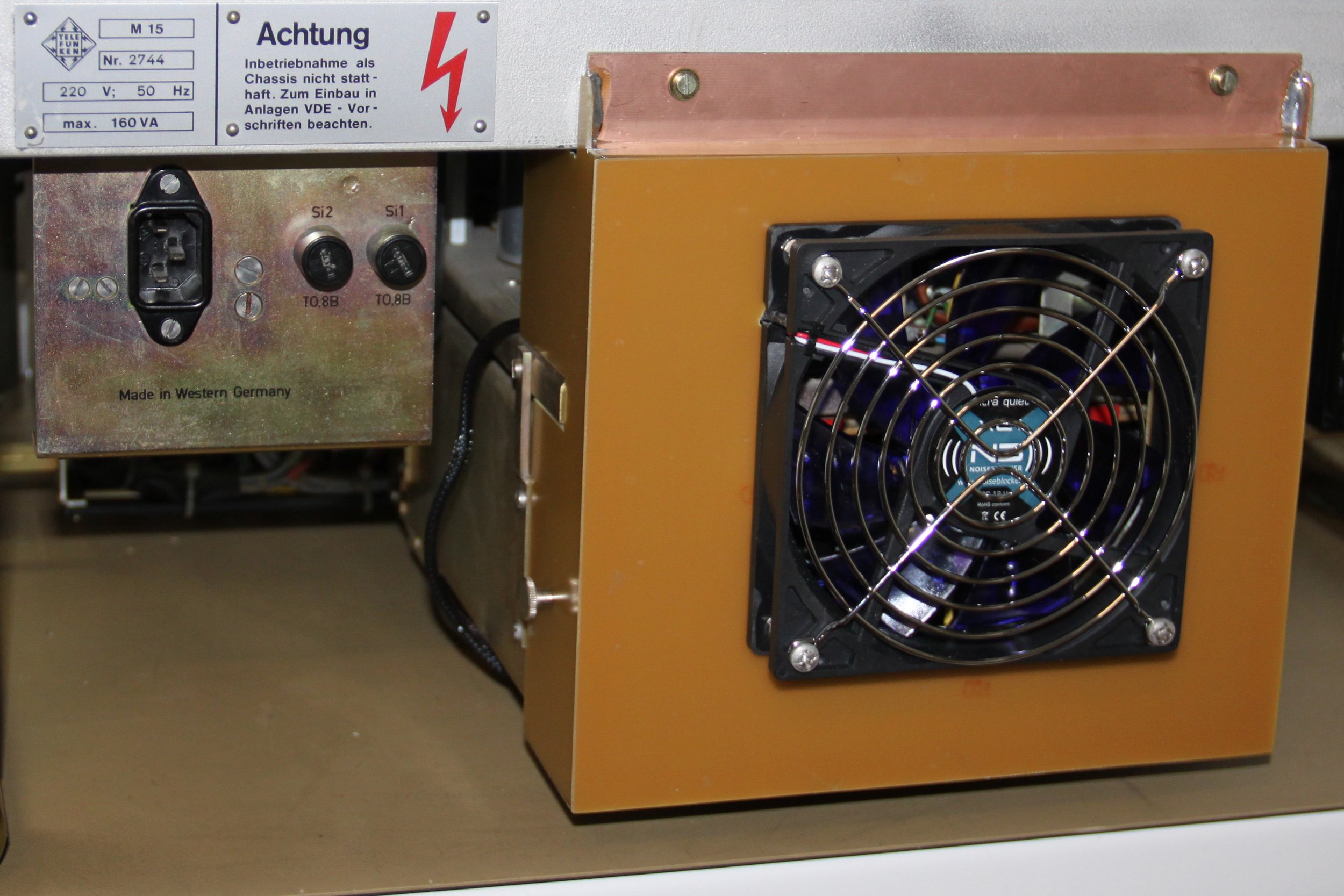
Figure 4: Fan unit

Figure 5: Two temperature curves with free-standing and covered M15, without fan

Figure 6: Temperature curve with and without fan at different operating conditions of the tape transport
Why a fan unit?
High temperatures drive the aging process of the electronics. With my almost 50 year old sweetheart, I paid special attention to these relationships and carried out temperature measurements in various environments. After all, it would be a great pity if after the high effort of recommissioning or restoration, the device would fail for such reasons. In the Telefunken manual, chapter 2.1., it says: "Additional ventilation by fans is not necessary". The technical data states that the device can be operated at an ambient temperature of + 5 to + 45 °C. My tests showed that the controller of my device did not work properly from a temperature of about 42 °C, measured at the rear of the chassis. I could not explain why this was the case and decided to use air conditioning. Supply and exhaust air must be provided in the sound-insulated case. For this case, I calculated that the whisper-quiet XL-1 fan from Noiseblocker with its 69 cubic meters of airflow per hour (1.15 m3 per minute) would be sufficient and bought a set with thermostat and power supply. For the extensive temperature tests, I attached the sensor of an electronic thermometer to the chassis above the circuit board unit of the drive magazine.
Figure 5 shows two different temperature curves: Once the M15 stands free and without a hood: The lower green curve shows the self-heating of the machine with the Capstan motor running and the belt transport stationary. The machine warms up by about 11 °C within six hours. If the machine is completely covered with a hood or mounted in a Telefunken K15A tape case, the temperature rises by 17 °C, i.e. 6 °C more than when free-standing (blue curve). If a tape is played in this operating condition, the thermometer scale rises by 9 °C within 2 hours. At 47 °C, I stopped the experiment in order not to provoke any defects. Freed from the cover, the machine cooled down quickly, as shown by the upper green curve. I have drawn in the critical area at 42 °C. Above this temperature, the control system may go crazy or a fuse may blow.
Further tests showed that a fan unit has to cool both back planes, i.e. the transformer with its components as well as the boards below. I produced precisely fitting pieces from epoxy resin boards coated on one side with copper, which were soldered inside to form a fan cassette (Fig. 4). The fan received a cutout true to size to keep airflow noise at protruding edges to a minimum. To attach it to the unit, I used four existing threads as well as the screws from the removed covers. The fan cartridge largely closes with the components on all four sides, allowing for sufficiently efficient airflow.
Compared to Figure 5, Figure 6 shows that the machine heats up similarly with the tape running when the fan is off (area at the top of the image marked with a red bar). At 36.3 °C (exactly 15 °C above ambient), I turned the fan on (area with green bar at top of image). Various operating states of the tape run followed. Result: The temperature of 30 °C is not exceeded when the fan is running. When the tape transport is at rest, the temperature settles at about 24 °C. This ensures that the M15 is cooled effectively even at higher ambient temperatures.
To keep the entry of dust low, the fan blows outwards. Below the magazine of the control boards I installed a filter cassette for the air intake. This was chosen to correlate with the fan in terms of pass-through capacity. The filter cartridge corresponds to category G3 in filter class EN 779:2012. The density of the fiber layers increases towards the clean air side (inside of the housing), which ensures optimum defined filter performance, dust holding capacity and air flow. Depending on the ambient dust and operating time, the filter mat must be checked at regular intervals and then cleaned or replaced.

Figure 7: Switch for reversible functions

Figure 8: Wiring for reversible functions
Locking the recording and switching off the counter
Often requested by users, but not implemented by Telefunken until the M15A: The lock of the recording function, to prevent accidental erasure of tapes. For this function, I cut a small circuit board, drilled it and attached it with two cable ties to the side rail in such a way that you can reach the switches even when the front cover is mounted. To preserve the originality of the unit, I avoided interfering with it (as I did with the fan cartridge), so that this function can be dismantled if necessary without leaving any traces. The toggle switch "rec" is used to turn off the center switch contact of the record button, thus disabling the function (red wires in Figure 8).
Since sometimes the clicking of the analog counter gets on my nerves or I want to spare it because I don't need the function when listening to a tape, the lamp for the pulse generator can now be switched off and thus the whole counting function is blocked (black cables in picture 8).

Figure 9: Connecting the remote control to socket 1 on the rear panel of the M15

Figure 10: Remote control with driver stage and relay (case opened), with power supply and connector
Text and photos: Claus Müller
Translated with www.DeepL.com/Translator (free version)
Remote control
The luxury of a remote control has the charm of being able to insert the tape, put on the hood, sit down and then start the music at your leisure. With the M15, it is very easy to control the start/stop operation remotely. Telefunken has taken precautions: In the manual "magnetophon 15, accessories, technical description", a very simple circuit diagram can be found on page 4, see picture 9.
For the connection, a 30-pin plug is required. Either one realizes this function via cable and switch or via an infrared remote control. I bought an cheap 4-channel remote control including transmitter. For the operating voltage of 5 volts I use an old USB power supply as used for charging smartphones. For the construction of such a remote control more profound electronic knowledge is necessary, because the circuit could not switch the relays I used without an additional transistor driver stage. The dark red tinted acrylic case blends in well. It can be seen in the lower right of picture 1. I replaced the supplied remote control with a nicer Seki model.