


The telcom c4 noise reduction system
Introduction
In 1975, the telcom c4 noise reduction system developed by Telefunken was introduced. It significantly improves the quality of analog magnetic tape recording by reducing the noise floor by up to 30 decibels (dB). Although the inherent noise of a signal cannot be eliminated with telcom c4, tape noise can be reduced. The principle is based on the compression of levels before recording, which are then decompressed to the opposite degree during playback.
Figure 1: Telefunken insertion carrier ES 4 with 2-channel compander insert telcom c4 F2H (2 pieces)
How does telcom c4 work?
In tape recording, there is a physical limit of approx. 60 dB signal-to-noise ratio or dynamic range. The telcom c4 noise reduction system extends this up to 90 dB. Figure 2 shows schematically how this works. If a signal with a dynamic range of e.g. 90 dB is copied to tape compressed with telcom c4, it can be archived in this encoded state. If it is decompressed during playback, the original signal is available again in its previous dynamic range. No quality restrictions are to be expected when using telcom c4.
Figure 2: Schematic representation of the tape copy process with and without telcom c4
When working without telcom c4, as can be seen on the right in Fig. 2, approx. 30 dB of the dynamic range is lost when recording to the magnetic tape and the studio music signal is then only available to a limited extent. Simplified, it can be said that the quiet parts of the music signal are lost in the tape noise.
Another advantage of the telcom c4 process is that it has a positive effect on the copy effect between the tape layers: pre- and post-echoes are significantly reduced.
Technical implementation telcom c4
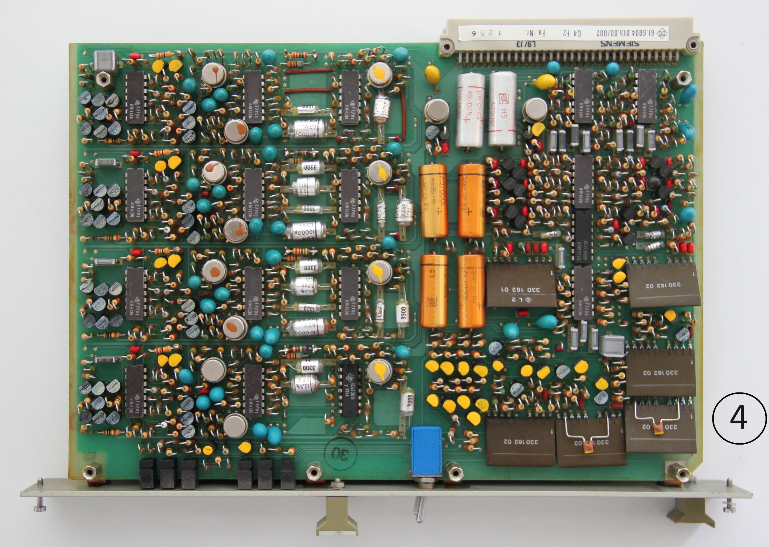
In order to realize the transient response of the control amplifiers on the telcom c4 boards in a range where no audible distortion occurs, a solution had to be found between the transient response and the decay, since this would be impossible with a single control system for the entire frequency range. Therefore, the range was divided into four frequency bands, each with its own control system. Figure 3 shows the four ranges schematically, and on the circuit board shown in Figure 4 these bands can be identified on the left-hand side by repeating rows of components.
Figure 3: Frequency bands telcom c4 with settling and decay times for a level increase and level decrease of 30 dB
Figure 4: Compander insert telcom c4 F2H
Figure 5 shows the measurement of the four frequency bands. They are within a tolerance band of 2 dB. This is a very good value. If the same device is used for encoding and decoding, the differences balance out due to the mirror-image effect of the electronic circuitry, because: The same circuit is used for encoding as for decoding, because it is switched into the negative feedback of an operational amplifier. This is another major advantage of telcom c4.
Figure 5: Linearity measurement of the four channels of a telcom c4 F2H compander insert at a level of -30 dBu.
Realization of telcom c4
The ES 4 rack with 2-channel telcom c4 F2H compander insert offers fully equipped four channels via two compander inserts, each of which can be switched as an expander or compressor. This allows two stereo channels to be encoded and decoded simultaneously. In practice, this means that if you have a tape machine with rear tape control, you can use telcom c4 to record in encoded form and then immediately control the signal in decoded form during playback. Figure 1 shows the setting of the switches on the front panel for this purpose.
The ES 4 slide-in carriers are sufficiently available on the second-hand market. Before buying, please make sure that they are fully loaded. However, the condition can vary greatly. The four boards, two per compander slide-in F2H, are cooled by a fan in the device. If this is defective, you can also expect defective boards with a high degree of certainty. A repair is difficult because the boards are packed with electronics and contain some special components. On the other hand, the four boards offer optimal conditions for comparative measurements during a repair.
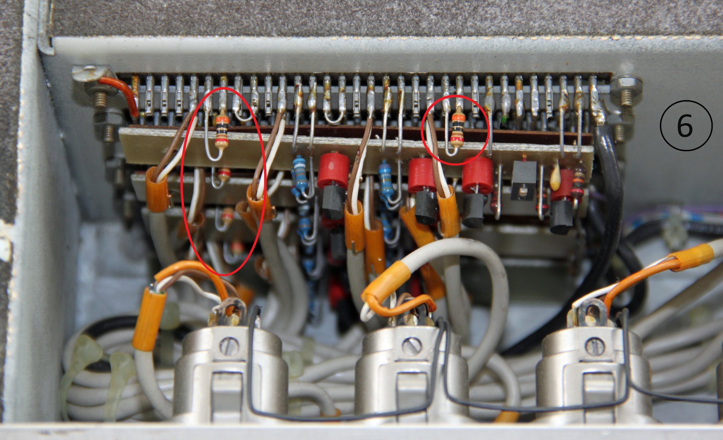
When restoring or recommissioning a Telefunken ES 4 rack, the question of the level ratios of the device is often asked. Figure 6 shows resistors of 3 kΩ soldered to the socket connectors, which are eight pieces when fully assembled. This is the standard value for a level preset of +6 dBu. You can also find devices with 6.8 kΩ (+2 dBu) on the market. Since the replacement of the resistors is very complicated, I would recommend to first check the whole device for proper function and then consider re-soldering them.
The control range by means of the soldered resistors can be between -4 dBu and +15 dBu. The values are calculated by a formula and refer to the voltage behind the dBu value. For simplification I have calculated here some levels in dBu, the corresponding voltage in volts, the calculated resistor according to the specifications for the Telefunken slide-in carrier ES 4 and the corresponding resistor value according to the E24 resistor table:
Table 1: Series resistance input and output Telefunken slide-in carrier ES 4.
Figure 6: Series resistors of 3 kΩ in telcom slide-in carrier ES 4 (circled in red, not all can be seen).
The AEG-TELEFUNKEN manual contains the following text on this subject: "The nominal level should be set so that it matches the sine-wave duration level from the reference band on the one hand and the nominal system level on the other. This results in no difference between telcom c4 "on" and "off" (55 Hz, 550 Hz, 2.5 kHz, 15 kHz) when leveling the entire system."
Measurement and reference curve
Figure 7: Measurement of telcom c4 compander insertions.
Compared to other developments where the characteristic curves are non-linear (e.g. Dolby), the telcom c4 method does not require leveling of the compander, which is a considerable advantage for operation.
Figure 7 shows the lines of the four channels as encoder and decoder respectively. On a logarithmic scale, the characteristic curve is shown linearly (as a straight line). For an instrument over 40 years old, the measurement results are excellent. The red line represents the reference line from which compression or expansion can be mirrored in the respective direction. Note that above the intersection of the lines, the mode of action is reversed: the compressor becomes an expander and the other way around. Although the headroom is improved, care must be taken not to record the compressed signal on tape at too high a level. Otherwise, it may happen that after decoding there is too high a level, which will cause distortion. It is recommended to reduce the recordings from 514 nWb/m to 320 nWb/m. In studio levels, this is then +2 dBu instead of +6 dBu, i.e. 4 dB less than the studio standard level for full scale ARD broadcasting (for series resistors, see Table 1).
Why telcom c4 in 2020?
In studio productions, digital master files are often copied onto an analog tape and then directly digitized again in order to remove a certain "digital harshness" from the signal and give it more punch. If these are sent through a tape machine without the telcom c4, tape noise would be perceptible in quiet passages and at higher volumes, and the dynamic range would be reduced to about 60 dB. If one now switches the telcom c4 compressor and expander in between, this noise remains below the perceptual limit and the original level is largely preserved. Sound restrictions are not to be expected.
Figure 8: Connection of telcom c4 ES 4 to tape machine with rear band control
AAA master tape copies
The original tapes of the Quinton label for the master tape copies of the Analogue Audio Association (AAA) are available in telcom c4 format and are only decoded during the manual dubbing process to the tape desired by the customer. Compared to many master tape copies circulating on the world market, the copies of the AAA tapes are very low-noise and thus meet a very high standard for tape playback.
Summary: Advantages of telcom c4:
No quality restrictions are to be expected when using telcom c4
The same circuitry is used for encoding as for decoding
Due to the linear characteristic curves, telcom c4 eliminates the need to level the compander
Pre- and post echo are significantly reduced
Translated with www.DeepL.com/Translator (free version)